Jump directly to main navigation Jump directly to content Jump to sub navigation

Overcoming the challenges of inline thickness measurement (Part 2)

ME448_Collage_Systems_1_header_900x370.jpg

When selecting an in-process thickness measurement system, a number of challenges need to be considered, including the effect of combined real world errors. In this second article on thickness measurement, Glenn Wedgbrow, Business Development Manager at Micro-Epsilon UK, discusses how these challenges can be overcome in practice.

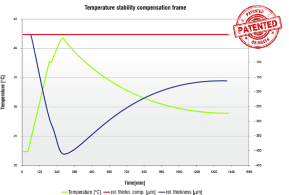
What is important when selecting a suitable thickness measurement system from a supplier is to understand the combined real-world errors that can occur when using a non-contact system and how these errors can be eliminated or compensated for. While many suppliers state on their datasheets that the measurement system meets a certain resolution and linearity, in the real world, this performance is affected by a number of environmental influences. Errors associated with real world thickness measurement are not always obvious, but can combine to create significantly large errors. It is therefore critical to select a system based on system accuracy, not just sensor accuracy.

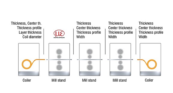
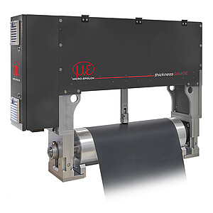
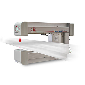
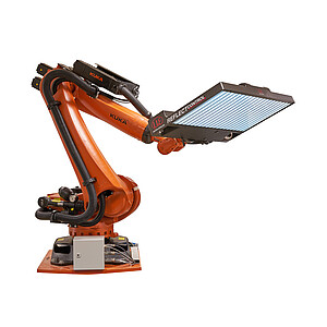
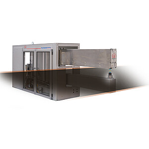
To overcome these challenges, as a systems supplier, we must take each application on its own and assess the needs of the customer, consider the tolerances required and whether sensors alone are able to solve the task. Our systems division is focused on thickness and width gauging solutions for strip processing materials including metals, plastics and rubber. All our key competences can be found within the systems division and so we are able to use the many different measurement sensor technologies from within the Micro-Epsilon group. We also develop our own software and algorithms, including all the automation, linear guiding, traversing and programming of robots. Most important is that we understand the mechanics of the systems we build, our knowledge of the surrounding environmental influences such as temperature and how to overcome these, which is critical to the success and continued operation of our systems. We now have more than 500 system installations worldwide.

So how do our systems solve the challenges of inline thickness measurement?

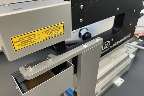
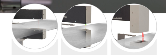
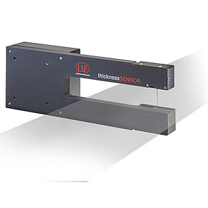
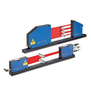
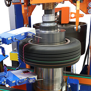
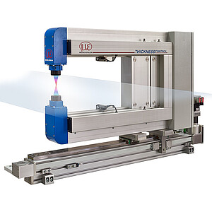
Two of the big challenges, alignment and synchronisation, are taken care of when purchasing a system from Micro-Epsilon. Knowing the overall gap or distance between the two sensors allows the calculation of thickness to be made. To establish this value, we first need to calibrate the system. A certified gauge block is positioned in the measuring path. This known thickness combined with the readings from the sensor above and below the target equal the overall measurement gap. Our systems will periodically return to the calibration position to check for changes and readjust values accordingly. Once the gap is confirmed and stored, the system can then be moved onto the target to be measured. The thickness of the material will now be the known gap, the sum of the individual measurements from the upper and lower sensor.

Thermal compensation

A typical system solution is a traversing C-frame measuring strip metal thickness for crown, wedge and edge drop on a decoiling line prior to slitting. Calibration checks against the certified gauge block are performed at regular intervals to avoid inaccuracies that may be caused by changes in the mechanical frame, for example, due to temperature.

Thermal compensation in an O-frame system works slightly differently. The gap between the sensors is key to accurate thickness measurement. Even in an O-frame configuration the mounting frame can expand and contract with temperature changes. Typically, the upper frame will move further than the lower frame, heat rises and so the reference for the gap between the sensors can vary, the consequence being that the system reports a thickness change even though the real thickness has not changed. Micro-Epsilon O-frame systems use a patented compensation frame made from an invar material and are designed so that thermal expansion of the frame is transferred in the horizontal direction rather than vertically. However, this is only part of the solution.

Thermally stable system

The second element is to measure the gap change between the main frame, which holds the sensors as this invar frame. This is achieved by using two Micro-Epsilon capacitive sensors, themselves extremely accurate and thermally stable. When the main frame expands or contracts, we can measure this change on the gap between both the top and bottom frame and compensate the effect into the thickness calculation. Even when the sensors are traversed across the full opening, the changing gap is continuously monitored and adjusted. As with the C-frame system, we also have a certified gauge block included that can be positioned into the measurement zone.

The effect of temperature change with no compensation employed can be significant.

A 25°C change in temperature is perceived as almost 400 micron change in thickness.

Optical sensors

Three optical sensor technologies are available for integration into the measurement systems. Single point laser triangulation sensors offer a relatively low cost entry into full thickness measurement capability. Confocal sensors provide the highest precision available, especially on shiny surfaces, whilst the laser line technology is the most commonly used due to its excellent combination of high precision and large measuring ranges. One of the main reasons for the use of laser line profile sensors is that we are able to make a best fit line of the multiple points taken from the surface. Even if some points are missing due to surface oils or textures, the average reading is still good and valid.

Another consideration in the use of the laser line sensors is that the laser line can compensate for tilts in the material. If single point measurement is used, there can be significant errors introduced by the fact that the measurement is no longer taken perpendicular to the surface. The line sensor allows for detection of the angle of the tilt and thus compensates to ensure the correct thickness value is measured. In addition, the laser line power/exposure time can also be adjusted to cope with oil films, emulsion and scale on the surface. It also offers the ability to measure profiled surfaces for both minimum and maximum thicknesses, which can be helpful in understanding the performance and wear of, for example, an embossing roller. A single point sensor cannot do this.

Advantages over X-ray and isotopic systems

The more traditional method of thickness measurement in the metals industry has been the use of Isotopic or X-ray gauges but these can have limitations when it comes to handling, ongoing support and operation. As we use optical measurement techniques, we are generally not restricted on the material type we can measure. Our measurements are made against a certified gauge block and we do not have to recalibrate for different material types. Isotopic or X-ray systems need to know the material type being measured due to material property changes that influence the systems’ measurement behaviour.

As well as the fact that we have no radioactive substance to handle or control, there is also no need for a safety area around the system, other than standard guarding.

Total system accuracy

Each individual sensor has its own measurement accuracy and therefore in order to obtain the best performance for the ‘system’ we need to understand the measurement behaviour of the individual sensors and combine them. This is achieved in the systems department through use of a known target and highly precise reference gauge, which is moved through the measurement range of the sensor. The values of the sensors are recorded and the combined readings stored into a new linearisation algorithm, which is used by the systems software to calculate the true thickness reading. This is the extra step needed to achieve the total system accuracy, which is often better than the quoted individual sensor performance.

The fact that we are measuring against a known target for calibration allows for the customer to perform their own capability checks at any time and to verify the system performance without influence from the supplier.

Each measurement system from Micro-Epsilon comes with fully capable software for operation, data capture and analysis of the required measurements. The multi-touch functionality provides a familiar user experience similar to many smartphones and touchscreens in everyday use. The software screens are customisable and can be adjusted for a customer’s own specific needs. The software also includes the means to check your system’s capability at the touch of a button, performing both reproducibility and repeatability checks whenever required and without supervision from Micro-Epsilon.

For more information, please visit www.micro-epsilon.co.uk or call the Micro-Epsilon sales department on +44 (0)151 355 6070 or email info@~@micro-epsilon.co.uk

For further information