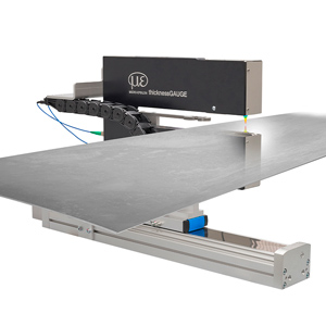
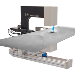
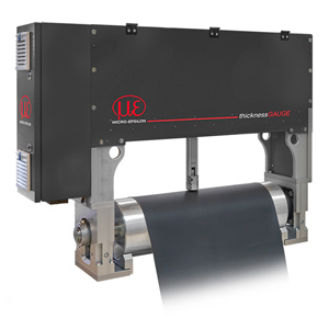
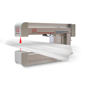
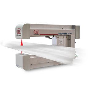
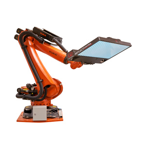
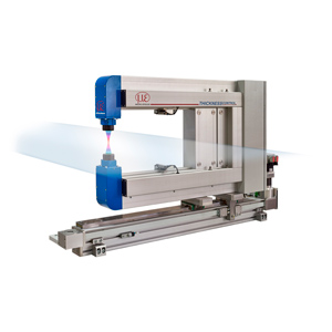
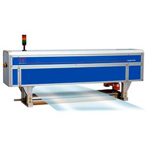
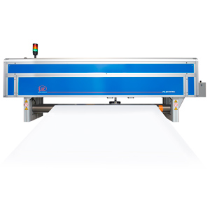
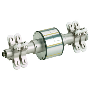
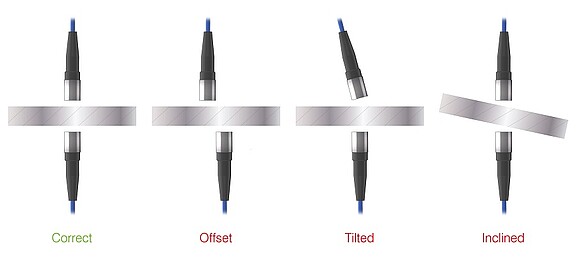
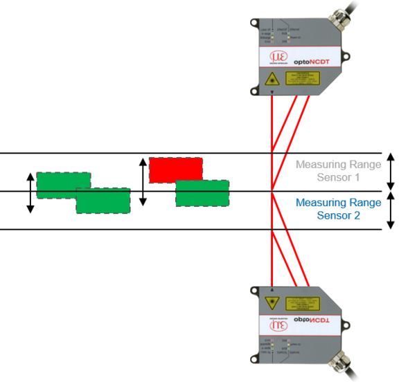
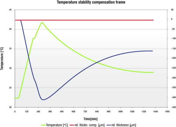
When selecting an in-process system for measuring the thickness of film, plate or sheet materials, a number of challenges need to be considered, including sensor alignment, linearity and the effects of thermal changes, says Glenn Wedgbrow, Business Development Manager at Micro-Epsilon UK.
There are many reasons why we need to measure thickness. All materials have a tolerance in production, so any materials that are too thin or too thick could cause a problem further down the line or at the end customer’s site. Changes in thickness during production can indicate wear of components, for example, in extrusion dies or on rolling stands. Monitoring trends can point to early warning signs.
The traditional method of checking thickness is often to take a measurement sample from the start of the production run and then again at the end. But what happened in the middle? If you find the material is out of tolerance, that’s a lot of scrap to consider. So you might choose to take more readings during the process. If these checks are being done manually, they often require the production line to stop. Most process variability will come in ‘start’ and ‘stop’ phases, so keeping a line running is generally key to improving consistency. Ultimately, checking the product thickness as it’s produced ensures that the end customer receives the quality of product expected.
Target material types and the production processes used all have a bearing on how the thickness of a product can be measured. Sometimes it is based on the setting of a gap on a roller or adjustment of dies in an extrusion head. It could be liquid poured and cured such as glass, rubber or metal. It could also be part of a secondary process where the basic material is already produced, but is then combined with similar or differing materials as multiple layers, or even woven strands that are then bonded such as carbon fibre.
Let’s now consider some of the challenges of measuring thickness.
Single-sided measurements
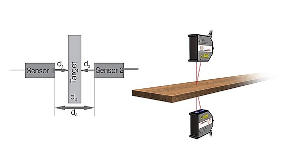
Perhaps the simplest thickness measurement is a single-sided measurement against a reference or datum surface. First, the sensor is zero’d on the datum surface and the target to be measured is inserted. The reading of the sensor is changed or displaced by the material thickness. There are a number of uncertainties with this method. If the reference or datum moves after mastering, the reading will be incorrect. Similarly, if the target does not sit correctly on the datum surface, the air gap will also be included in the measurement. The same issue can also occur with tilted targets.
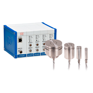
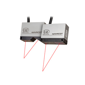
If we are only allowed to view a target from one side, we must consider if we can combine technologies to enable accurate measurements. Where we have a mix of different material types, we can utilise those different material properties to our advantage. For example, an eddy current sensor in combination with a laser triangulation sensor can be used to measure sprayed skin thickness. The eddy current sensor measures the distance to the nickel-coated spray mould and has an opening in the centre through which the laser sensor measures the distance to the sprayed part. Eddy current sensors only measure against metallic targets and therefore see straight through the non-metallic sprayed coating. The use of an air coil in eddy current sensors from Micro-Epsilon makes this combination possible, as the laser sensor can look through the eddy current sensor at the same measuring point. When both signals are subtracted, the thickness of the applied sprayed skin is measured.
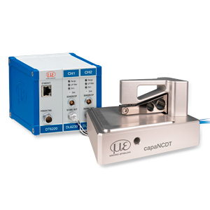
Another well used sensor combination is achieved with eddy current and capacitive sensors for non-metallic materials passing over a roller. Movement of the metal roller is considered by the eddy current sensor and the capacitive sensor measures the material or coating thickness.
Single-sided measurements – special case
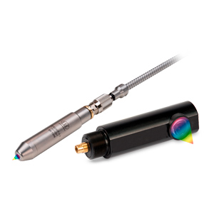
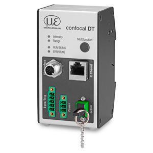
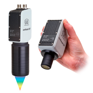
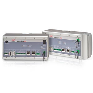
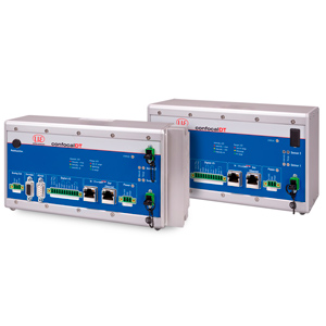
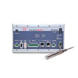
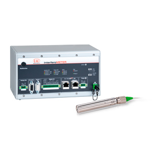
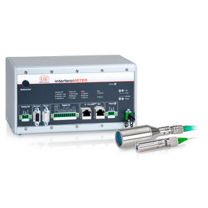
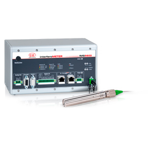
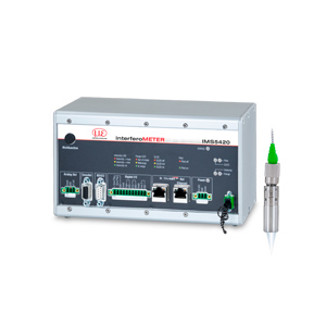
If the target is transparent, it is possible to make an absolute measurement of the material thickness from one side using only one sensor with Interferometer or confocal technology.
The use of light refraction creates ‘edges’ or return signals that indicate the transition between the air and the material. Knowing the refractive index of a material enables the accurate measurement of the material thickness provided it stays within the measurement or working range of the sensor.


