Configuration Tools - easy setup for scanCONTROL laser scanners
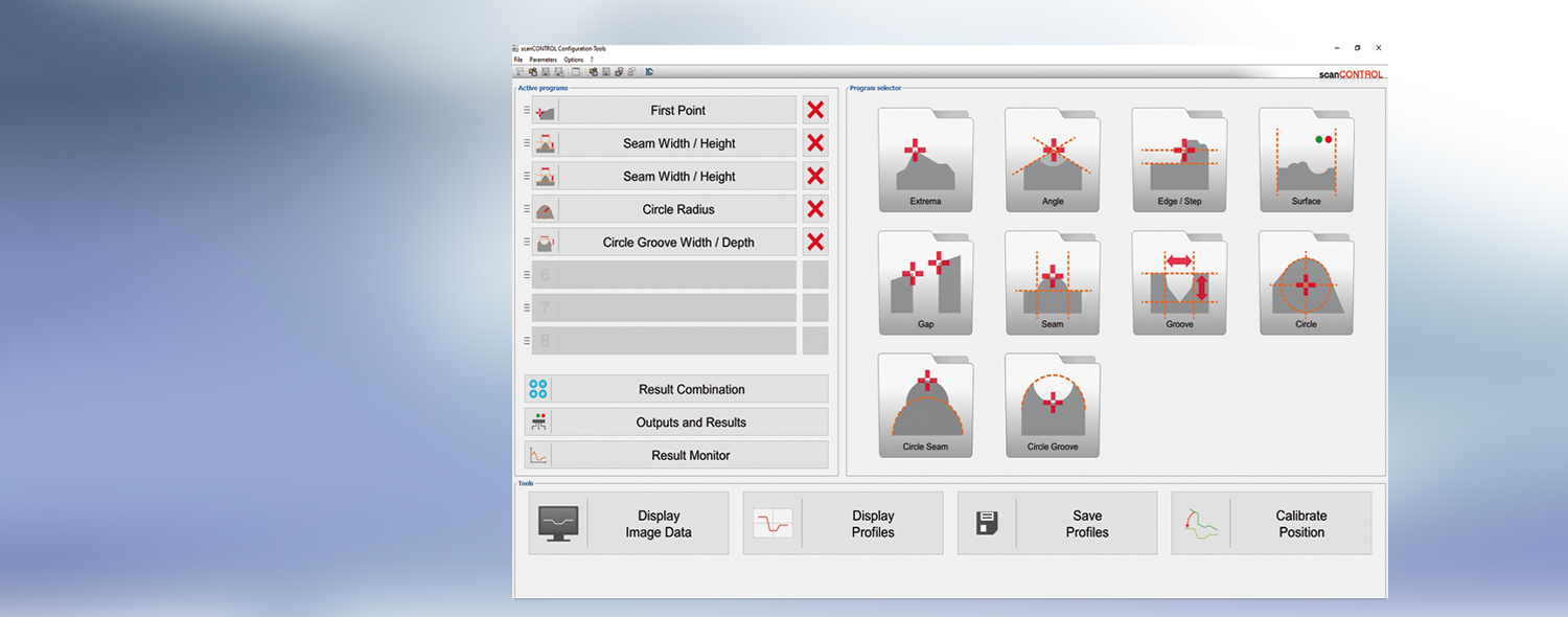
scanCONTROL Configuration Tools is a software to configure scanCONTROL sensors on a Windows PC. It helps you to set up the sensor, view profiles, save/load and export profiles.
In combination with scanCONTROL SMART sensors, the Configuration Tools software unfolds its true power. It parameterizes complex measuring tasks including all outputs via the corresponding interfaces.
Set up scanCONTROL profile sensors
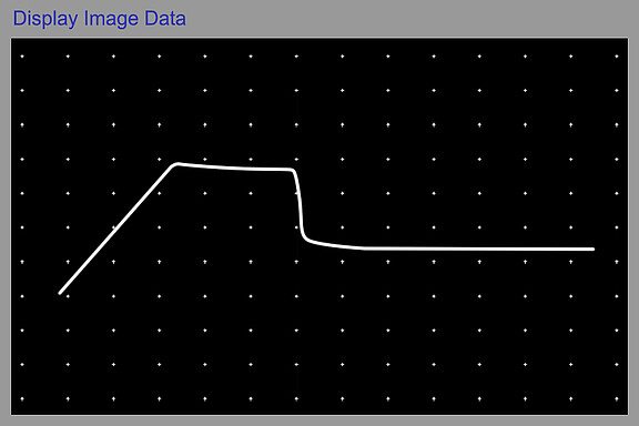
scanCONTROL sensors offer numerous parameterization and setting options, which can be carried out using the scanCONTROL Configuration Tools software. It provides e.g. direct access to the image of the sensor matrix in order to achieve an optimum basis setup. The live image of the matrix is used to optimize the alignment of the sensor in relation to the target.
Display, save, load and export profiles
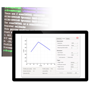
One profile consists of up to 1280 calibrated measuring points depending on the sensor type. These profiles are transmitted via FireWire or Ethernet to the PC. scanCONTROL Configuration Tools provides the possibility to display or save these profiles in real-time. Especially for very fast processes it is an absolutely necessary feature, because it is also possible to load the profiles again and analyse the profiles step by step afterwards. For further analysis it is also possible to export the profiles into a format compatible with MS Excel.
Plug&Play solution for measuring tasks
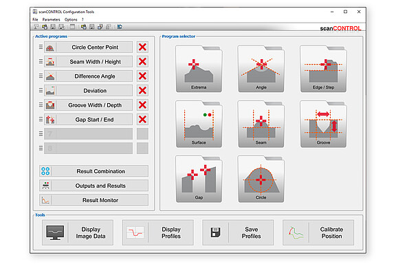
The SMART series sensors are equipped with intelligent controllers for basic profile evaluations without additional hardware. The Configuration Tools software is designed for easy parameterization of SMART sensors. The idea is to divide a measuring task into separate measurements such as e.g. edge, angle, gap, groove or seam. These separate measurements are combined to complex measuring tasks on the graphical user interface and evaluated. Therefore, the user benefits from a Plug and Play solution for individual tasks without requiring any programming skills. From version 6.0 and higher, these measurement tasks can also be stored on gapCONTROL scanners.
Parameterization of measuring tasks
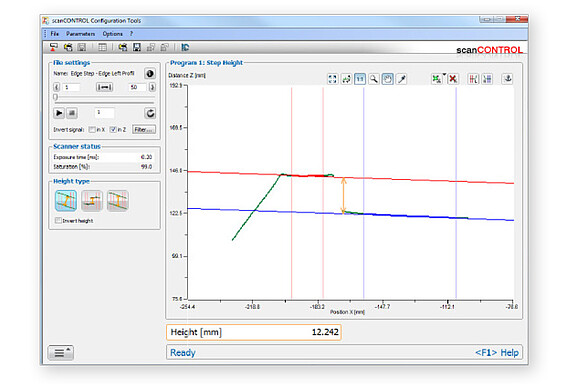
Configuration tools offers about 30 basic programs to choose from and which can be easily and quickly configured with only a few mouse clicks in the profile. The set parameters and results are immediately displayed on the screen. To measure an angle for example you simply choose two reference lines where the angle is calculated in between. Each measuring program also provides the possibility to cut out interesting sections in the profile. For dynamic measurement tasks also an individual dynamic tracking for each program is available and can easily be configured using an anchor point.
Data processing
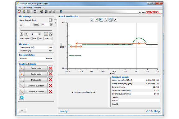
Once the individual measurement task parameters have been set up, the respective results are calculated together additionally. This provides a simple method of calculating, for example, several angles or distances between points or lines against each other, or to project points onto lines. Without tedious external computations, measurement tasks can be solved that cannot be covered by one single measurement program. The sensor directly outputs the measured values in real time. Thus, there are nearly no limits to the flexibility of calculating measurement values.
Analysis program for measurement value sequence
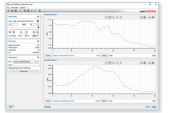
Using the "Result Monitor" analysis tool, measurement value sequences of recorded profiles and live profiles can be displayed and analyzed, enabling the evaluation of measurements. Additionally, an integrated cgm analysis (capability gauge measurement), and further statistical parameters (e.g. limit value exceeded, average values) are available.
The software allows for these values to be exported for archive purposes or for further analysis in calculation tables.
Outputs and results
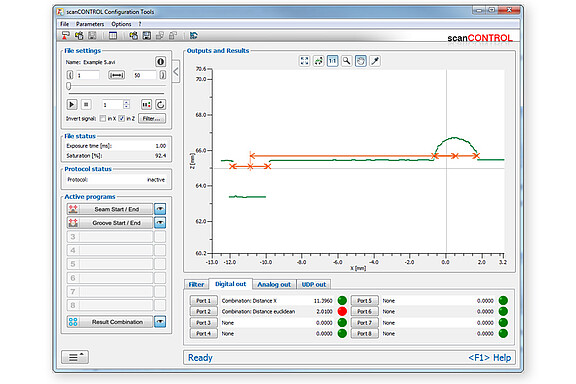
After all required programs have been configured, the software provides an overview of all measured results. By defining limit values, a good/bad evaluation is also possible, but in complex cases it is also possible to carry out logical operations (links with AND, OR, XOR) to check several conditions.
The user decides how to transfer the results from the sensor, e.g. via Ethernet UDP, Profinet or as digital OK/NOK signal, stores these settings in a complete parameter set in the head of the SMART (or gapCONTROL) sensor and can then disconnect the sensor from the PC. The profiles are then analyzed directly on the sensor without PC.


